 en
 简体中文
 Español
 Deutsch
 عربى

Cuplock Scaffolding Design in the USA: Load Classes, Ties and Bid Details
Content
- 1 What a cuplock node actually controls
- 2 Start with the duty load, not the tube
- 3 Metric cups, imperial lumber
- 4 Foundation, ties and bracing
- 5 Where aluminium makes more sense than steel cuplock
- 6 Access and egress: the detail that sets plan dimensions
- 7 What belongs in a US bid package
- 8 When standard cuplock runs out of answers
- 9 The design decision, restated
A contractor in Ohio priced a parking garage on 8 ft by 5 ft cuplock bays, the same spacing used on the previous job. The engineered drawings came back at 6 ft by 4 ft with an extra row of ties, and the labour estimate moved nine percent. That is the practical shape of cuplock scaffolding design in the USA: the system name is identical everywhere, but bay spacing, tie pattern and base detail are project-specific outputs.
The short version: cuplock design in the USA is a document, not a shape. Four decisions drive it, the duty load you declare, the cup increments on the standards you own or buy, the base and tie conditions at the site, and the access method at every level. Get those right and cuplock erects faster than most frame systems. Skip one and a tower that looks perfectly plumb will still fail inspection.
What a cuplock node actually controls
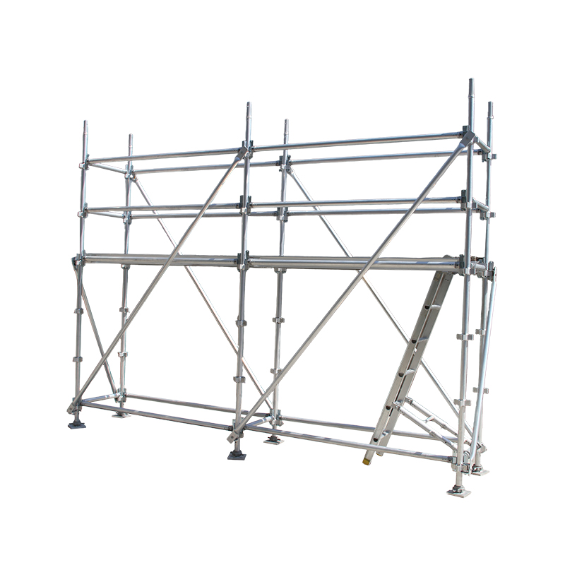
A cuplock standard carries a fixed bottom cup near the base and a sliding top cup. Ledger and transom tubes end in forged blades; the blade seats in the bottom cup, the top cup drops over it, and a wedge locks the joint. One node accepts up to four horizontal members at 90 degrees plus a diagonal, which is why the system tolerates irregular geometry better than fixed-angle rosette systems.
Cup position is also a design constraint. Cups are welded at fixed increments, commonly 500 mm (19.7 in) on centre, so the lifts available to you are the ones the standards provide. Standard lengths from 1.0 m to 3.0 m give a defined set of working heights. If a drawing assumes a 6 ft 6 in lift, the crew either lands on the 2.0 m cup or shims, and shimming changes the load path. Design lifts around the standard lengths, not the reverse.
Start with the duty load, not the tube
In the United States, the working load on a platform is declared before anything else is calculated. OSHA 1926.451 sets light, medium and heavy duty values, and 1926.451(a)(1) requires every component to support four times the maximum intended load. The declared class drives bay spacing, the number of ledgers, and the leg load that reaches the ground.
| Duty class | Design live load | Typical use on US projects | First check in design |
|---|---|---|---|
| Light duty | 25 psf (1.2 kN/m2) | Painting, electrical rough-in, inspection | Leg load at the highest lift |
| Medium duty | 50 psf (2.4 kN/m2) | Masonry, facade work, general trade access | Ledger bending and node slip at the wedge |
| Heavy duty | 75 psf (3.6 kN/m2) | Concrete formwork support, stone and precast | Base plate bearing and foundation capacity |
Two notes. A heavy duty classification does not by itself make a scaffold suitable for formwork support, because shoring carries its own assumptions about concrete pressure and pour sequence. And mixing classes on one tower confuses the crew, so declare one class per lift line and mark it on the elevation.
Metric cups, imperial lumber
Cuplock is a metric system and American sites are not. Scaffold-grade plank sold in the USA is nominal 2x10, which measures 1.5 in by 9.25 in, and OSHA requires plank to extend between 6 in and 12 in past its supports, or to be cleated. Guardrails sit at 42 in plus or minus 3 in, with a midrail halfway and toe boards at least 3.5 in tall. None of those numbers divide neatly into a 500 mm ledger system, so plank and guardrail layouts have to be detailed separately from the tube layout.
Interchangeability is the second issue. Blade thickness, cup depth and wedge angle vary between manufacturers, so cups and blades from different sources sometimes seat and sometimes do not. Verify the interface before frames go up; a blade 1 mm too thick in a cup 1 mm too shallow produces a joint that never fully closes, and it will show as a gap at the wedge on every lift.
Foundation, ties and bracing
OSHA 1926.451(c)(2) requires scaffolds to be supported on base plates and mudsills, or another firm foundation. On a finished slab that means base plates, a mudsill board where point loads demand one, and screw jacks kept inside the manufacturer's extension limit. Most US drawings keep usable jack extension under 12 in, so the standard can be levelled without side-loading the jack.
Tie spacing is the item most debated on site, and there is no universal number, because the correct pattern is a calculation. Free-standing height is limited by the ratio of height to least base width, commonly 4:1; above that, the scaffold must be tied or guyed. Engineered cuplock drawings for US projects show a tie map with vertical and horizontal intervals, the tie hardware, and the anchor or embedment method. Where the structure is a bridge deck, a tank shell or a curtain wall that cannot take a horizontal pull, the tie design changes again.
Bracing is the third leg: vertical diagonals in the end bays and at intervals along the run, plus ledgers at every lift, keep the frame from racking. A cup node makes bracing convenient, not automatically sufficient; the drawing decides which bays need diagonals in both directions.
Where aluminium makes more sense than steel cuplock
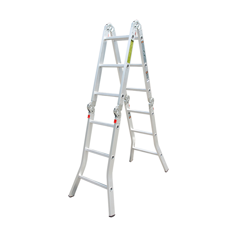
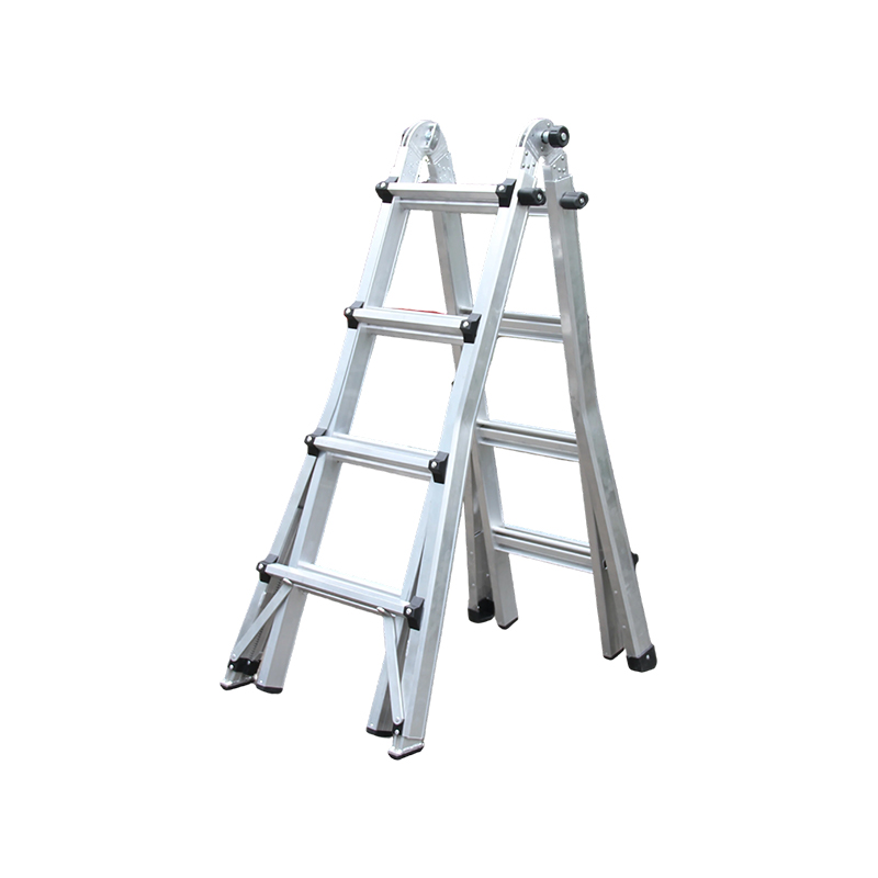
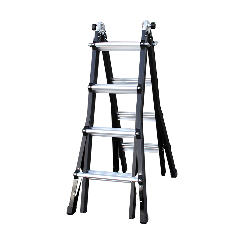
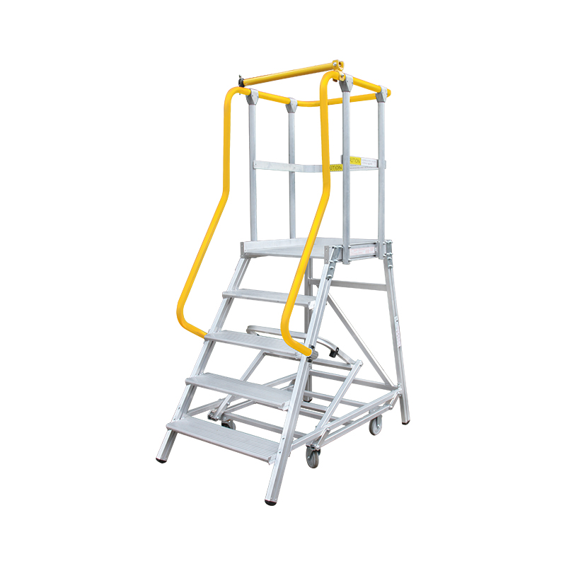
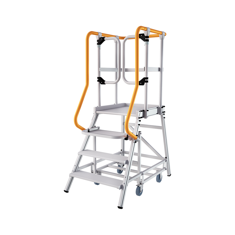
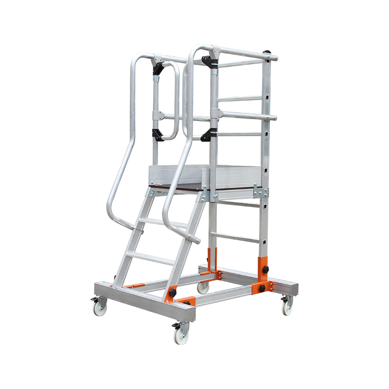
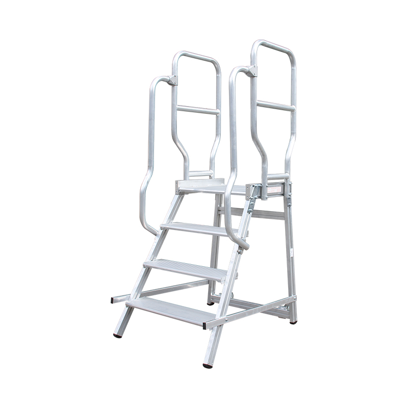
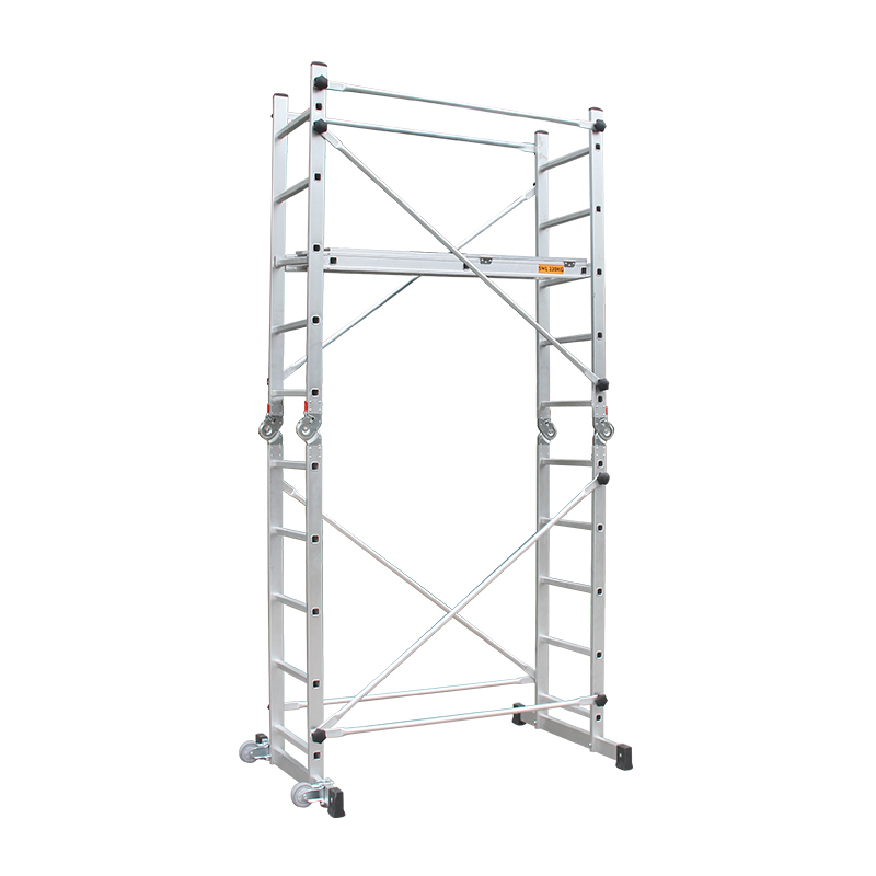
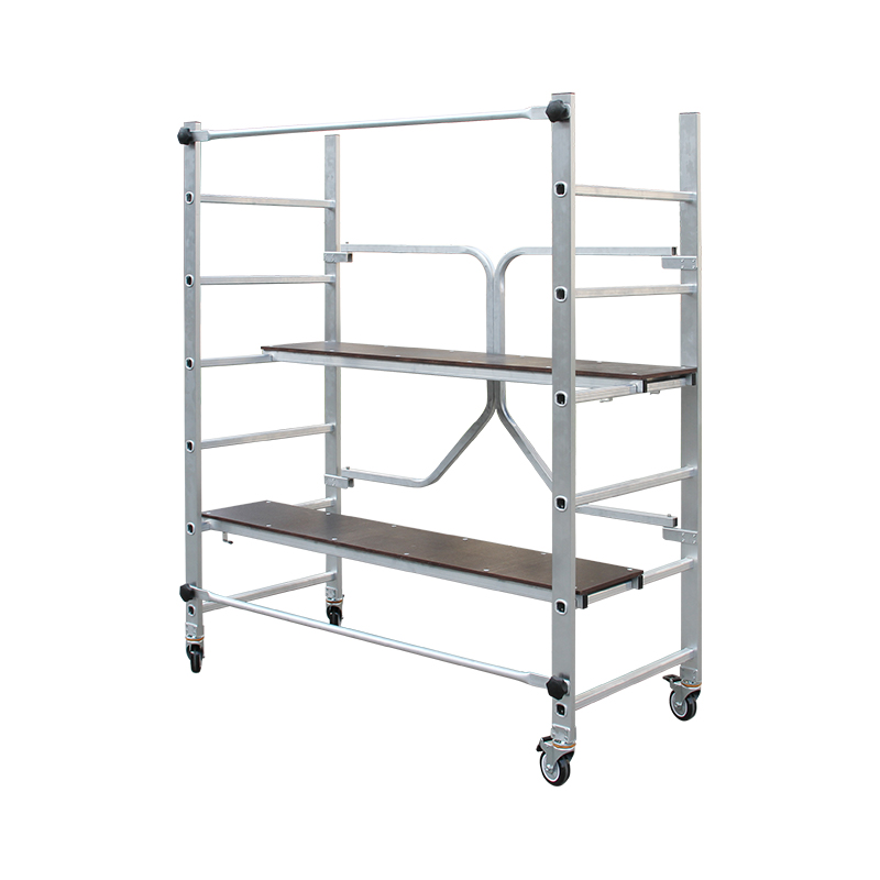
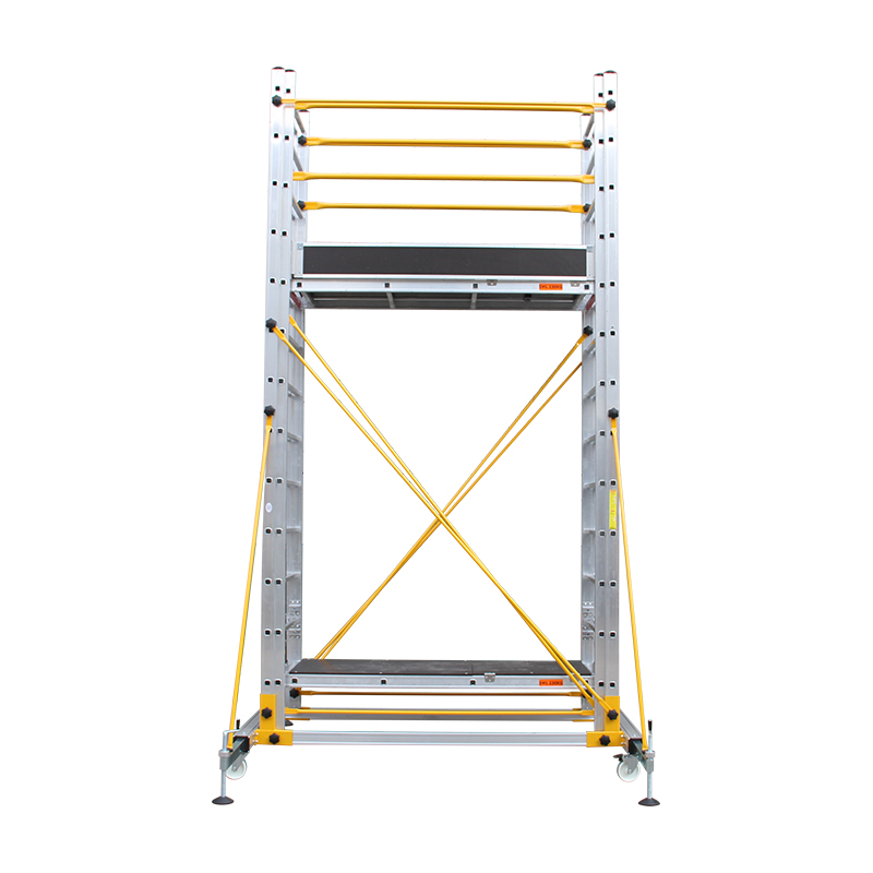
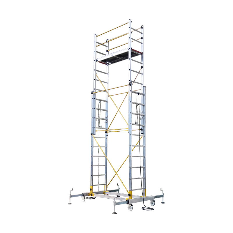
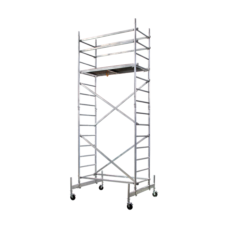
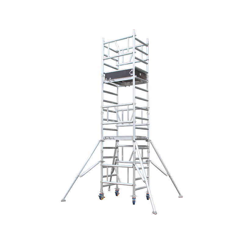
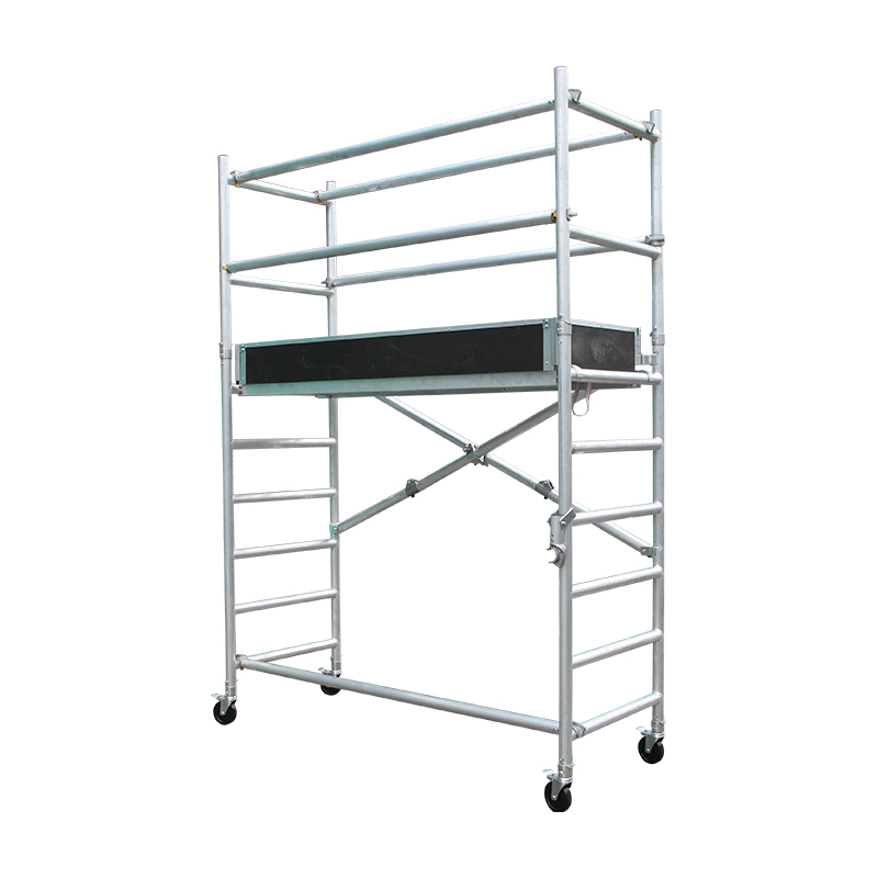
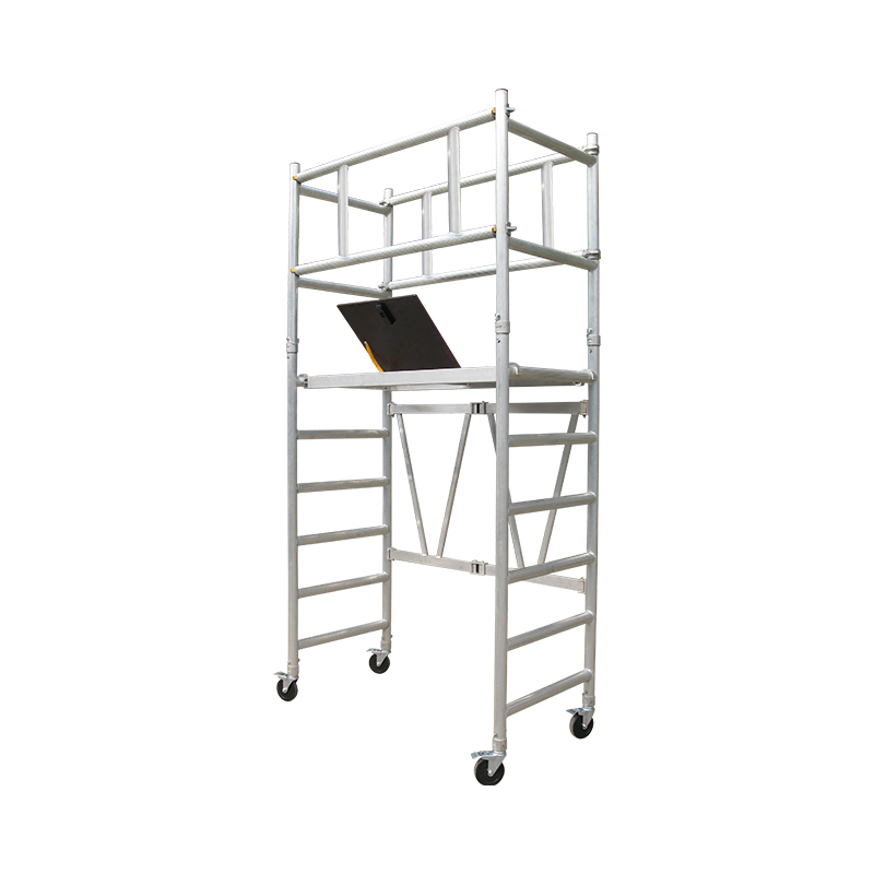
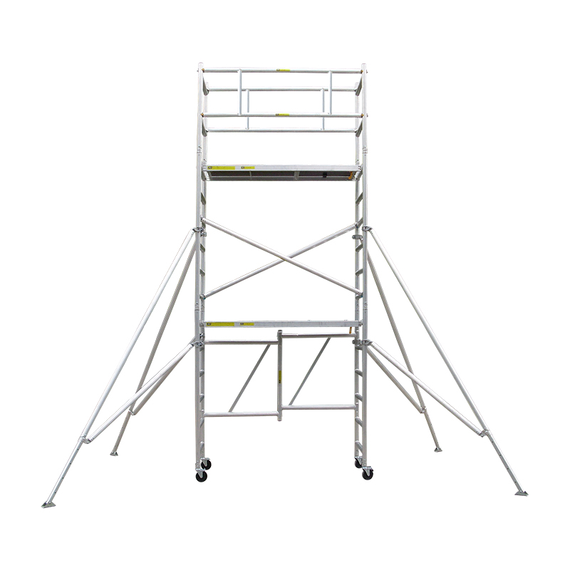
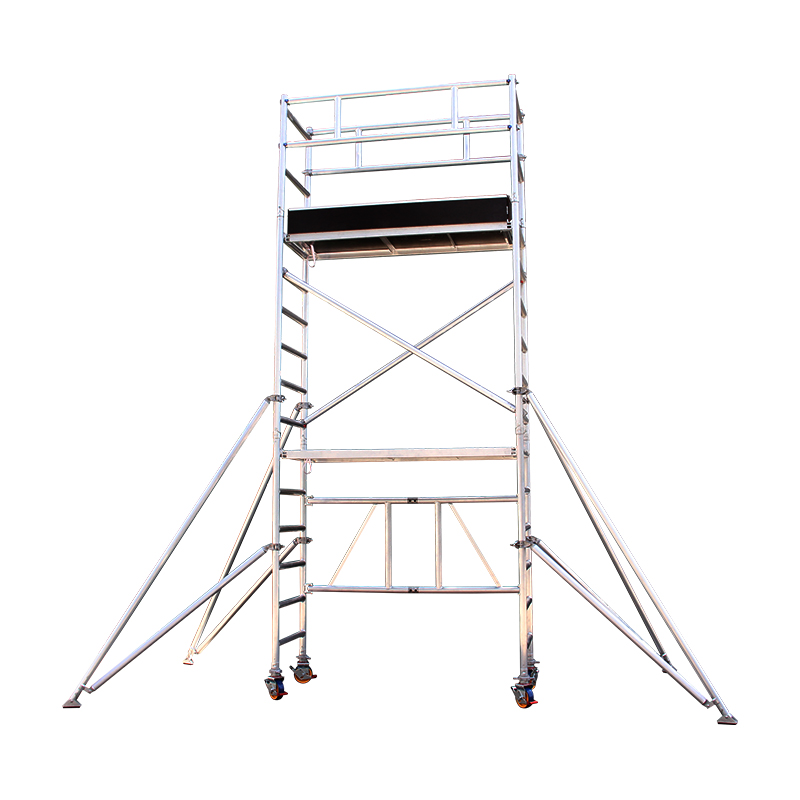
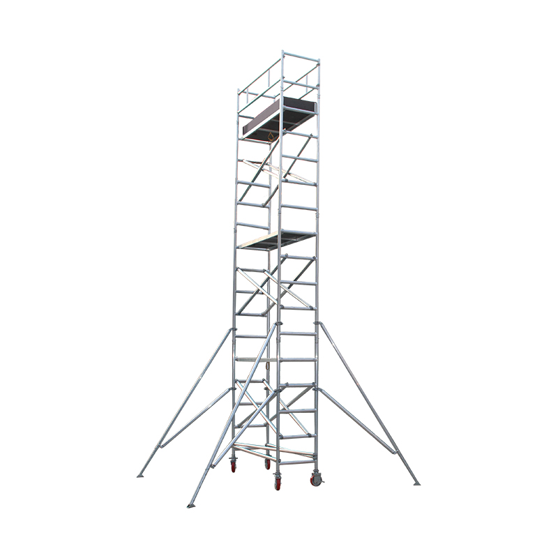
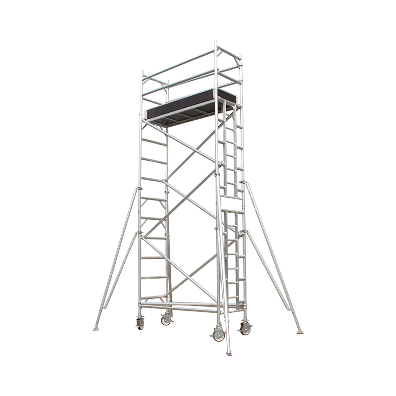
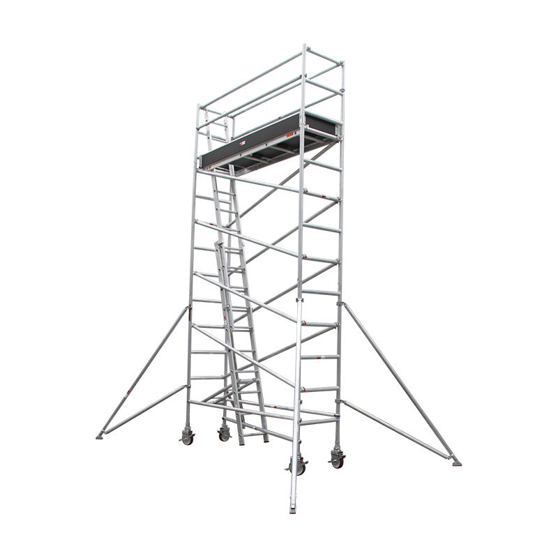
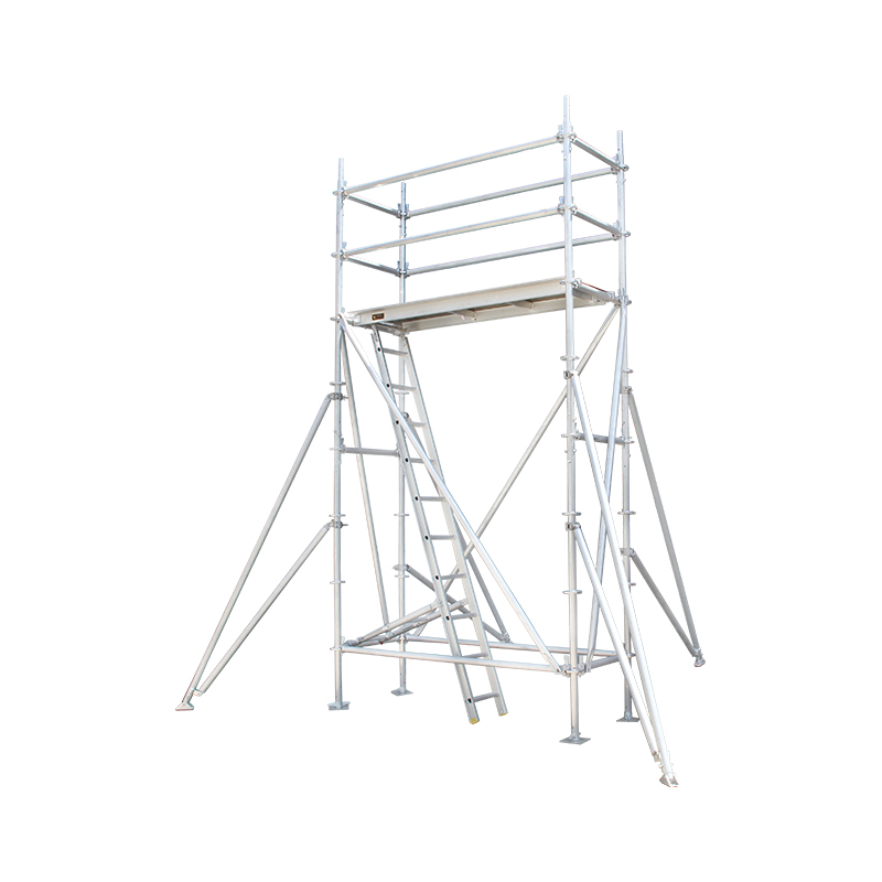
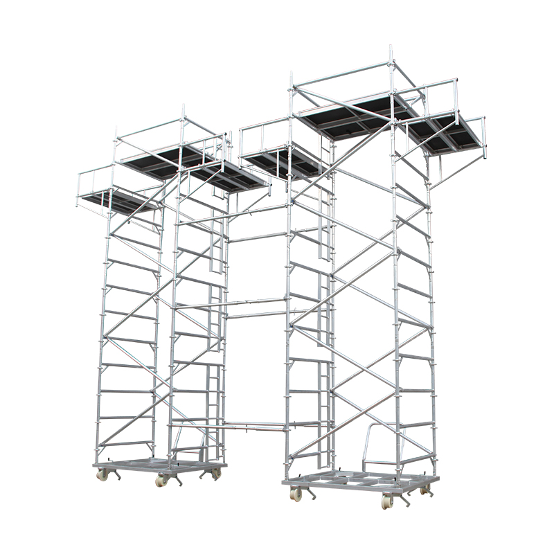
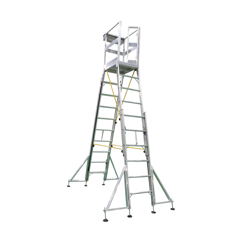
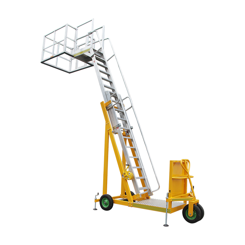
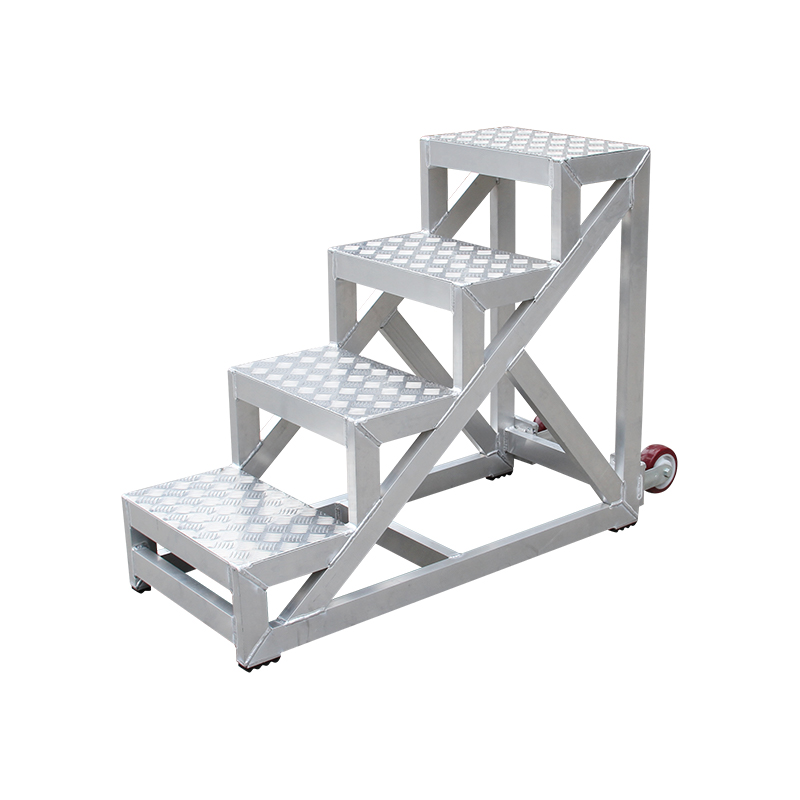
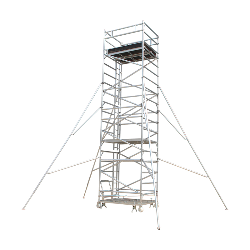
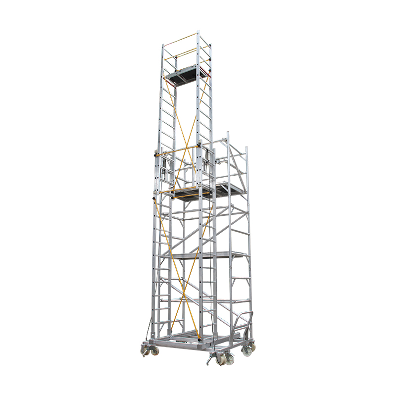
Steel cuplock covers the heavy end of the range: bridge falsework, concrete shoring, industrial maintenance where 75 psf is real. Aluminium has a different job. Aluminium mobile towers weigh roughly half as much per component as galvanised steel, roll into position with one or two people, and suit interior fit-out, MEP work, plant maintenance, and aviation or rail access where the deck is finished and the lifting equipment is a passenger lift rather than a crane.
The trade-off is allowable load. Aluminium towers are normally rated in the light to medium range, with tighter height-to-base ratios than steel cuplock. If the drawing demands 75 psf across a 20 ft deck, aluminium is the wrong answer. If it demands repeatable access at 25 to 50 psf inside a building that cannot take a two-tonne frame, it is the right one. A practical comparison of configurations is set out in our guide to aluminium mobile scaffolding types and uses.
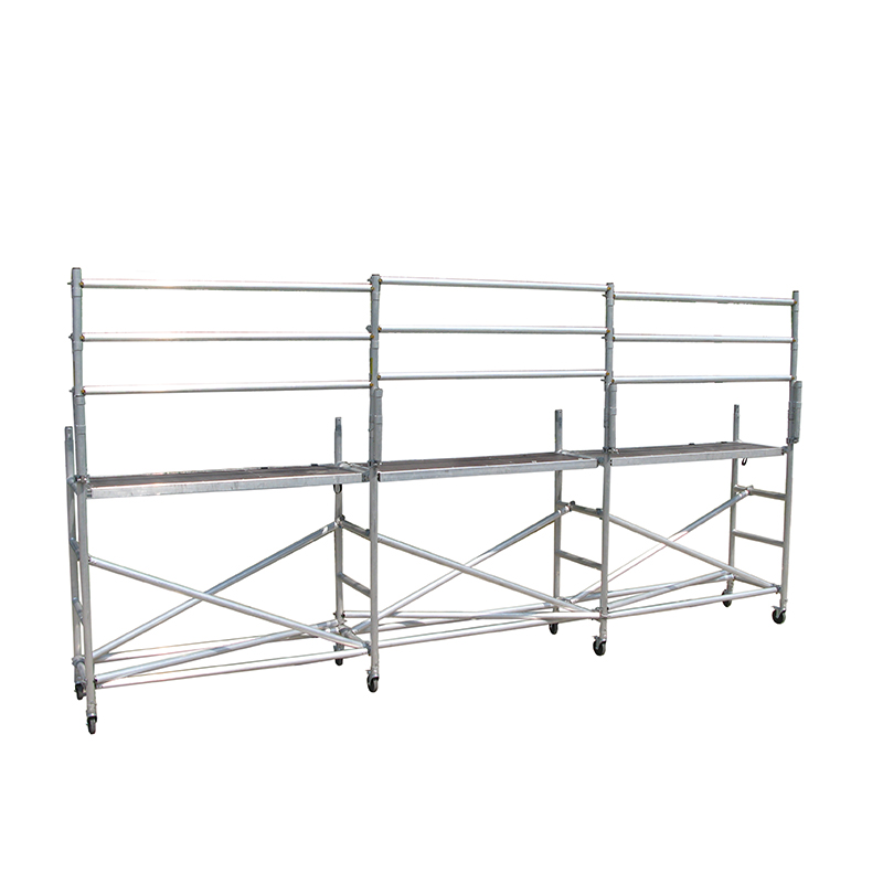 Aluminium Modular Scaffolding Systems for Working at HeightCategory covering custom aluminium modular scaffolds and Kwikstage, Ringlock, and Combined series for manufacturers and buyers planning safe access systems.View Product →
Access and egress: the detail that sets plan dimensions
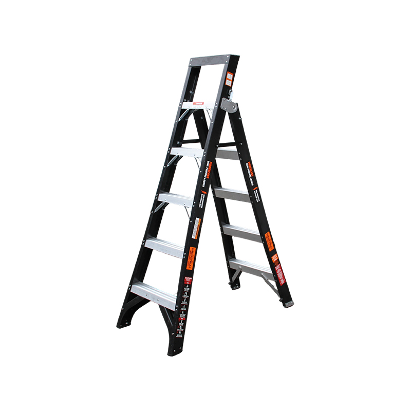
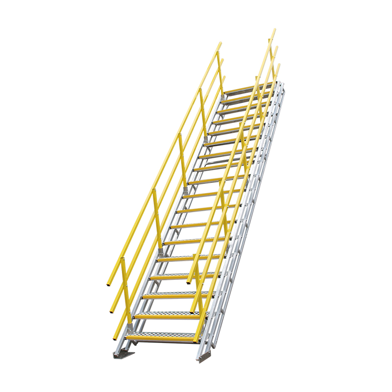
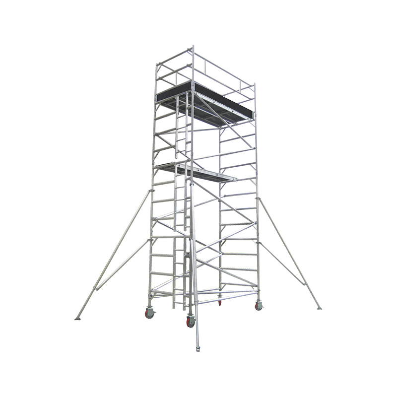
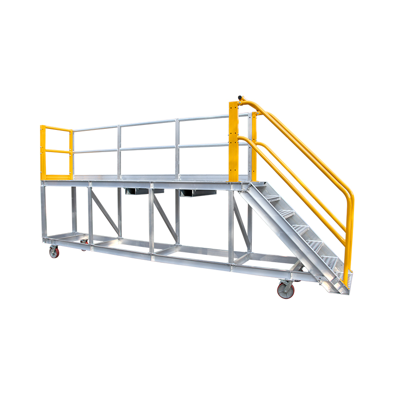
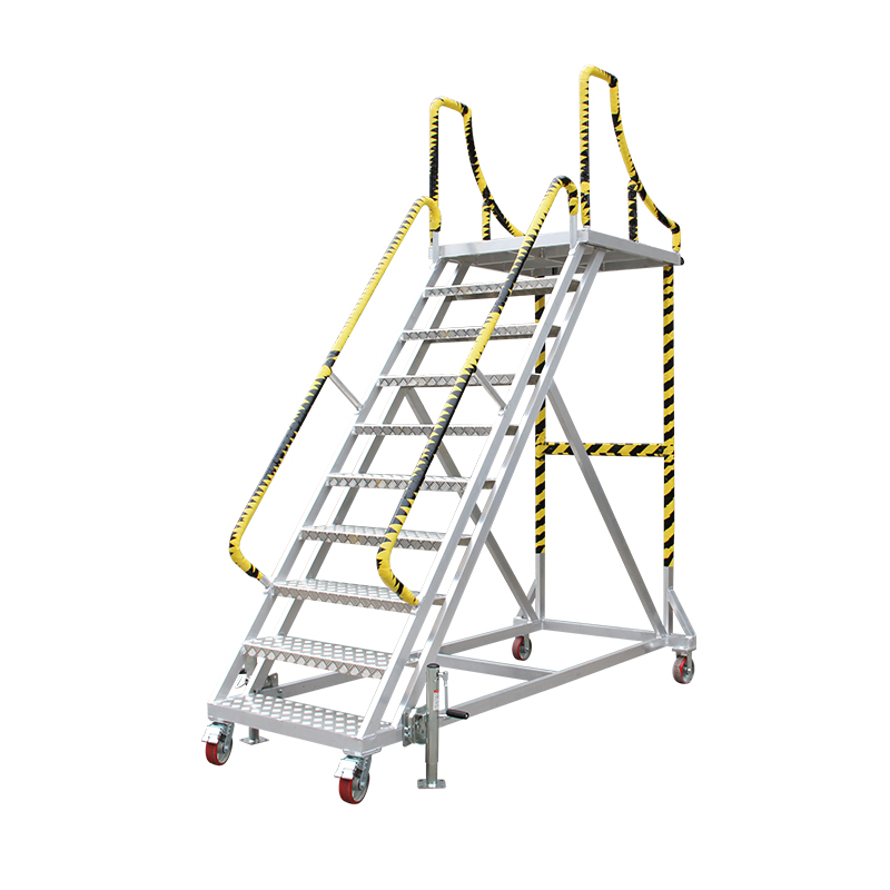
Above roughly 35 ft, cuplock access usually means a ladder frame bay, an inclined ladder bay with landings, or an internal stair tower. Stairs cost more tubes and more width, but they remove the ladder-cage debate, keep both hands free for tools, and shorten the walk to the work face. Ladder bays are cheaper per bay, but need a rest platform at the interval the drawings specify and a self-closing gate at the platform edge. Either way, the access bay takes vertical load and changes the bracing pattern, so it belongs in the design rather than the erection plan.
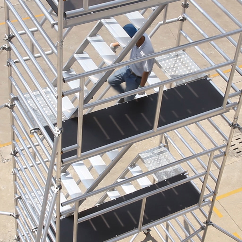 Double Width Aluminium Mobile Scaffold with Built-In StaircaseAluminium mobile scaffold with an integrated staircase, 14.2 m maximum working height, and EN 1004 standard for frequent level changes on site.View Product →
What belongs in a US bid package
- Drawings from a qualified person showing lifts, bay spacing, tie map, bracing and base detail.
- Allowable leg load charts for the exact standard lengths and lift heights proposed.
- Tube and component specification: steel grade such as ASTM A500 Grade B or C, wall thickness, and hot-dip galvanizing to ASTM A123 for fabricated parts.
- Weld standard and inspection records, with AWS D1.1 as the usual reference for structural welds.
- Node slip and wedge retention test reports, spare cup, blade and wedge pricing, and delivery or landed cost terms.
Origin documentation is not paperwork trivia. Federally funded bridge and transit work can carry domestic content conditions, and a supplier that cannot document where the material was manufactured puts the schedule at risk regardless of the quoted price.
When standard cuplock runs out of answers
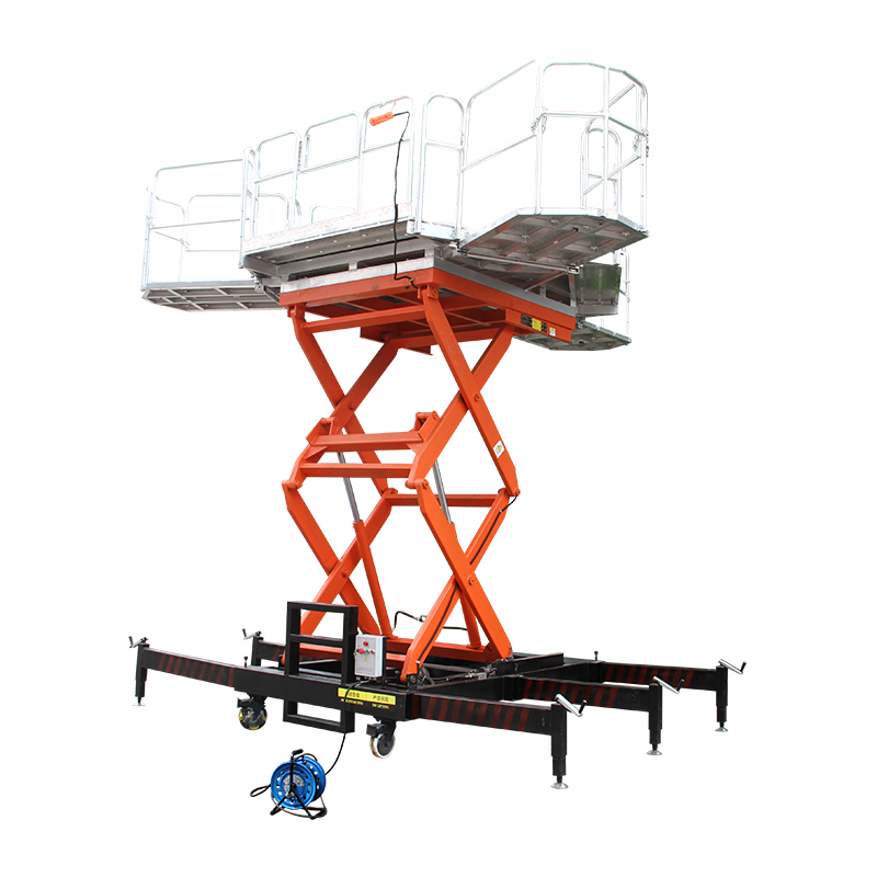
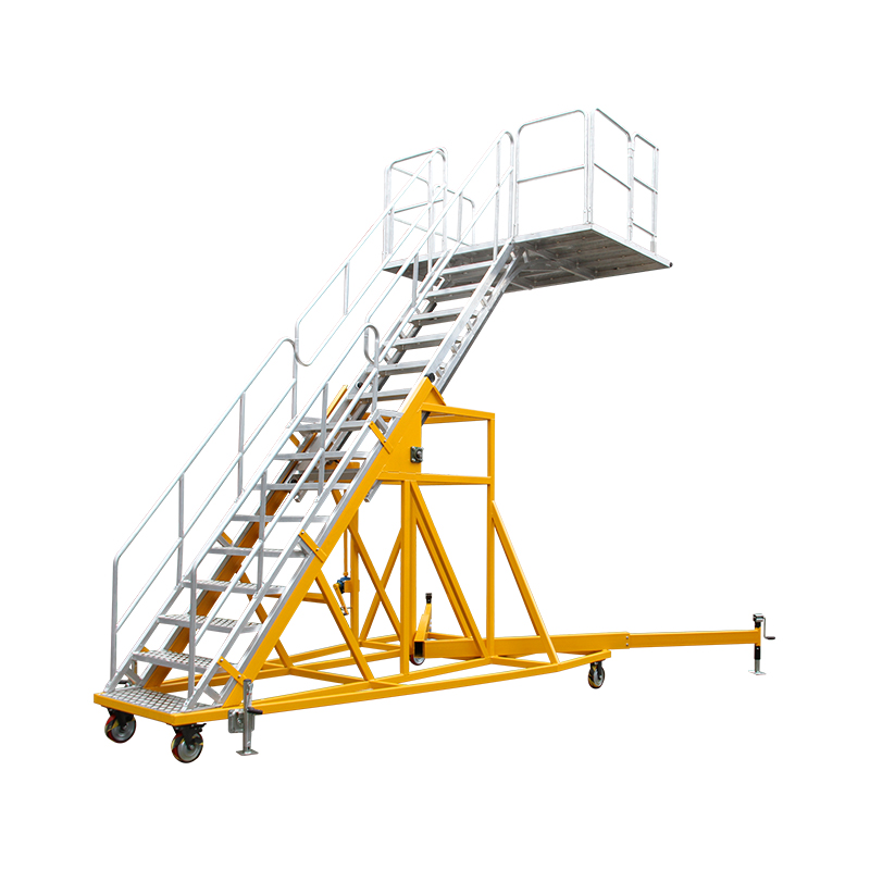
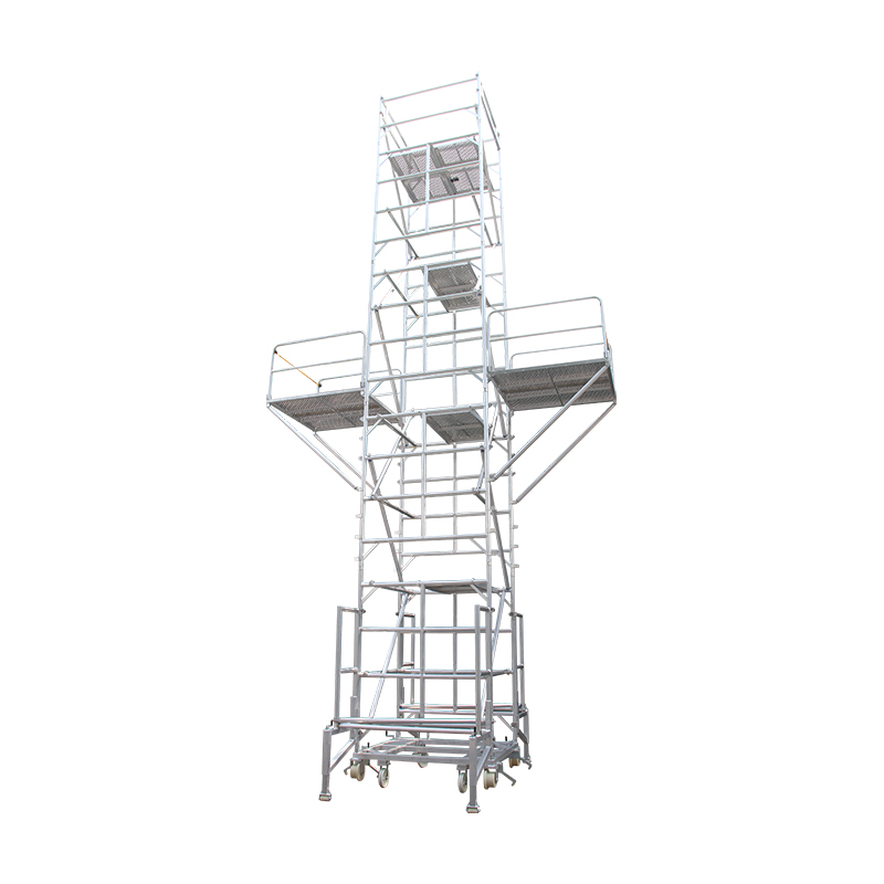
Irregular geometry, catenary access along a rail corridor, aircraft boarding steps and plant stair towers rarely match a catalogue bay. At that point the design moves from selecting a configuration to fabricating a component: a non-standard transom, a platform with a cut-out, a cantilever bracket, or a stair that lands between two fixed levels.
Tolerance discipline matters most here. A bracket 3 mm out will not seat in a cup already at its wedge limit, and a landing 10 mm out will not meet a fixed platform. Ask for shop drawings before manufacture, agree the datum points, and specify tube grade and galvanizing exactly as you would for catalogue items. Our custom fabrication work covers ladders, platforms and access structures built to project drawings.
 Custom Railway Scaffolding Access Platforms for Rail MaintenanceCustom aluminium access platforms for rail transit and train maintenance, with platform heights from 3.7 m to 12 m and project-specific engineering.View Product →
The design decision, restated
Cuplock scaffolding design in the USA is a set of numbers before it is a product: a declared duty load, a lift schedule that follows cup spacing, base and tie details that match the structure, and an access method that fits the plan. Steel cuplock covers the heavy end of that range. Aluminium covers the access end with far less weight to handle and far less equipment on site. Set the numbers first, choose the system second, and the drawings, the inspection and the labour estimate will all agree.
- Aluminium Mobile Scaffolding: Types, Load Ratings, Safety, and Buyer's Guide View more
- Cup Lock Scaffolding: Node Mechanics, Load Limits, and Installation Choices View more
- The 2025 Annual Meeting and Standards Review Conference of the National Technical Committee on Standardization of Machinery Safety was held in Ningbo. View more
- The 2025 Annual Meeting of the President's Office of the High-Altitude Safety Equipment Branch of the China Machinery Industry Safety and Health Association was held in Shanghai. View more
For project inquiries, fill in the form or contact us directly—our team responds promptly.

Copyright @ Shanghai Ruiju Metal Products Co.,Ltd. All rights reserved Aluminum Scaffolding Suppliers Aluminium Ladder Manufacturers
